USB cable holder
15 May, 2015
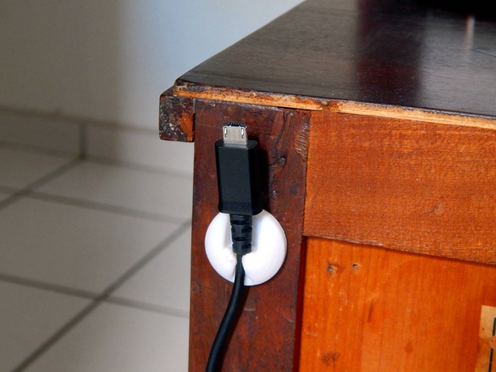
Hidden support for my cell phone charger cable fixed on the back of my nightstand. Nice stuff!
Source: http://www.thingiverse.com/thing:598446 ( or here )
Hidden support for my cell phone charger cable fixed on the back of my nightstand. Nice stuff!
Source: http://www.thingiverse.com/thing:598446 ( or here )
Hello there ESP8266, you've just got a new fan!
The first time I played with ESP8266 "Wifi to Serial" module I used my USB-to-UART cable and Ubuntu, very straight forward.
For starters, two things to have in mind:
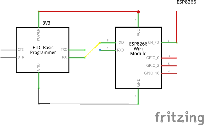
Having said that, wire both modules like schematic below:
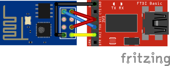
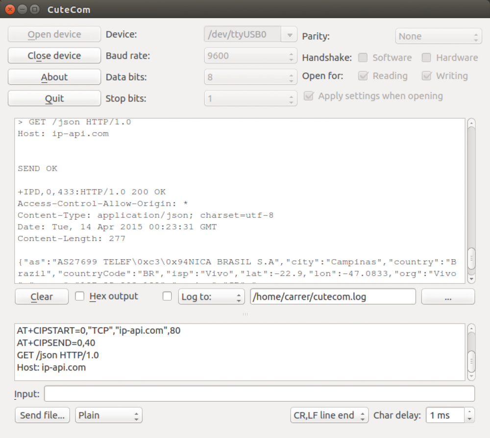
I confess I could not get minicom to work properly with this module, so I used cutecom (apt-get install cutecom) instead. You can get plenty information about this module at https://nurdspace.nl/ESP8266, so I really recommend taking a look at it.
In this example I connected to the ESP, listed all Access-Points available, connected it to my personal AP and consumed an online Geo-IP API service with it. (Connection settings can be seen/checked at screenshot below)
Command history:
// restart the module, just in case
AT+RST

OK
7!aS\0xcaS:\0xf1\0xfe\0x01\0xd91\0xb51\0x19\0xe2\0xd9\0xe6\0x0c<\0xff@b\0xe0
[Vendor:www.ai-thinker.com Version:0.9.2.4]

ready

// STAtion/client mode
AT+CWMODE=1


OK

// list all APs in within antenna's field area
AT+CWLAP

+CWLAP:(4,"Rep. Rancho Fundo",-X,"cc:a4:62:df:43:f0",1)
+CWLAP:(3,"Kakaroto4",-X,"28:c6:8e:b3:a7:12",1)
+CWLAP:(4,"RepX",-X,"c4:6e:1f:6d:7e:fc",6)
+CWLAP:(2,"raegui",-X,"c8:3a:35:1b:3b:98",6)
+CWLAP:(3,"sergioveio",-X,"5c:57:1a:22:6d:70",6)
+CWLAP:(4,"dlink-00F0",-X,"90:94:e4:fe:00:f0",2)
+CWLAP:(4,"SuiteMasterPranda",-X,"70:62:b8:80:4e:a3",6)
+CWLAP:(4,"arc",-X,"fc:b0:c4:d2:eb:7e",5)
+CWLAP:(4,"WakaWaka",-X,"e8:94:f6:eb:ba:10",6)
+CWLAP:(3,"net virtua 123",-X,"00:1d:d6:51:f5:d0",6)
+CWLAP:(4,"Dado",-X,"1c:7e:e5:be:7b:c6",6)
+CWLAP:(0,"S20CAM",-X,"00:40:96:57:99:32",8)
+CWLAP:(3,"EDSON A",-X,"00:1d:d5:01:c7:70",9)
+CWLAP:(1,"A.C.",-X,"00:23:cd:11:5e:b2",11)
+CWLAP:(3,"HP-Print-38-Deskjet 4640 series",-X,"a0:48:1c:65:5a:38",11)
+CWLAP:(4,"apto 113",-X,"70:54:d2:94:c9:9e",11)
+CWLAP:(4,"Zuza-Wireless",-X,"14:cf:e2:13:05:20",11)
+CWLAP:(4,"Chines",-X,"f4:ec:38:a0:74:bc",11)
+CWLAP:(4,"ed5a1c",-X,"d8:97:ba:87:82:bb",11)
+CWLAP:(4,"AP 133",-X,"a8:9d:d2:18:ee:0e",11)

OK
// setup connection
AT+CWJAP="SSID","PASSWORD"


OK
// check IP received by DHCP
AT+CIFSR

10.0.0.103

OK
//set mutiple connection
AT+CIPMUX=1


OK
//setup TCP connectin on Port 80 at domain ip-api.com on connection id 0
AT+CIPSTART=0,"TCP","ip-api.com",80


OK
Linked

//using connection id 0, send the following 40 bytes (which will be a GET request on /json resource, similar to http://ip-api.com/json)
AT+CIPSEND=0,40

> GET /json HTTP/1.0
Host: ip-api.com


SEND OK

+IPD,0,433:HTTP/1.0 200 OK
Access-Control-Allow-Origin: *
Content-Type: application/json; charset=utf-8
Date: Tue, 14 Apr 2015 00:23:31 GMT
Content-Length: 277

{"as":"AS27699 TELEF\0xc3\0x94NICA BRASIL S.A","city":"Campinas","country":"Brazil","countryCode":"BR","isp":"Vivo","lat":-22.X,"lon":-47.X,"org":"Vivo","query":"xxx.xxx.xxx.xxx","region":"SP","regionName":"Sao Paulo","status":"success","timezone":"America/Sao_Paulo","zip":"13083"}

OK$ wget http://downloads.arduino.cc/arduino-1.6.3-linux32.tar.xz
$ tar -xJf arduino-1.6.3-linux32.tar.xz
$ sudo mv arduino-1.6.3 /opt
$ sudo rm -f /usr/bin/arduino
$ sudo ln -s /opt/arduino-1.6.3/arduino /usr/bin/arduino
$ sudo usermod -a -G dialout yourUserName
$ sudo gedit /opt/arduino-1.6.3/hardware/arduino/avr/boards.txt
Add optiboot parameters for boards (take a look here to see all configurations available) you have at the end of file:
##############################################################
atmega328o.name=[Optiboot] Arduino Duemilanove or Nano w/ ATmega328
atmega328o.upload.tool=avrdude
atmega328o.upload.protocol=arduino
atmega328o.upload.maximum_size=32256
atmega328o.upload.speed=115200
atmega328o.bootloader.tool=avrdude
atmega328o.bootloader.low_fuses=0xff
atmega328o.bootloader.high_fuses=0xde
atmega328o.bootloader.extended_fuses=0x05
atmega328o.bootloader.path=optiboot
atmega328o.bootloader.file=optiboot_atmega328.hex
atmega328o.bootloader.unlock_bits=0x3F
atmega328o.bootloader.lock_bits=0x0F
atmega328o.build.mcu=atmega328p
atmega328o.build.f_cpu=16000000L
atmega328o.build.core=arduino:arduino
atmega328o.build.variant=arduino:standard
$ gedit ~/.local/share/applications/arduino.desktop
Add file contents:
[Desktop Entry]
Name=Arduino
Comment="Arduino IDE 1.6.3"
Exec=arduino
Icon="/opt/arduino-1.6.3/lib/arduino_icon.ico"
Terminal=false
Type=Application
StartupNotify=true
$ sudo desktop-file-install ~/.local/share/applications/arduino.desktop
$ ln -s ~/.local/share/applications/arduino.desktop ~/Desktop/

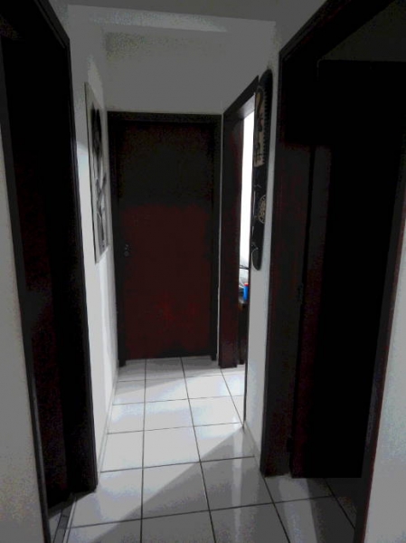 I have a nice "carranca" (or wall mask) from Chile that stands in my corridor. It's a very beautiful decorative mask that I liked from the very first moment I saw it at the shop. Few weeks ago I wondered if I could bring it to life by adding a motion sensor and some lights in it, since it has three convenient holes (two for the eyes and one for the mouth) and enough space on the back for housing wires, batteries and stuff.
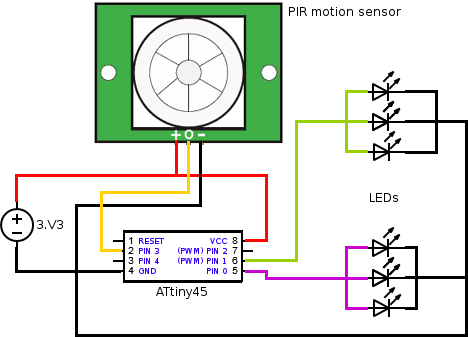
The circuit that I had in mind for my ATtiny has very simple: a digital signal from a PIR motion sensor would come in one pin, another pin would send a digital signal out for the lights. At the end, the only change I made was to use two different pins for the eye-lights: a PWM one for the left eye, another PWM one for the right eye. (PWM so I could fade LEDs in and out, and independently from each other).
Another thing that I had clear is that I was going to use interruptions and power-save-mode for saving me the trouble of switching battery every day.
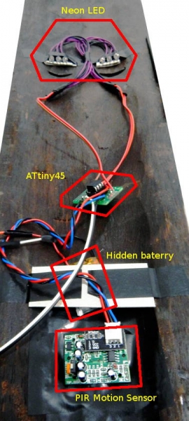 As shown on the picture on the right, I used 3 neon LEDs for each eye. There's some interesting to point out here: I had to aim the LEDs straight towards the wall so it could reflect the light and make it visible from in front of the mask (if I aimed the LED downward or straight to the mouth's hole, it would not work).
I'm using a small 3V 180mAh battery taken from a broken IR-radio-controlled helicopter from about over a month by now and it's still shining bright.
Source code: mask.ino
The result:
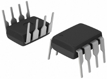 I'm a big enthusiast of the ubiquitous computing concepts, specially when they go related to the disappearing computing ("designed to exploit rich combinations of invisible (or embedded within everyday objects) sensing/computational entities”). As Mark Weiser said, "the most profound technologies are those that disappear", and to achieve that, things get to get smaller. And that's what I like the most about the "ATtinies". The Attiny45/85 8-DIP has about 1 cm2 and consumes 300µAh on active mode (that means if we use a common 3V CR2032 that can typically provide 220mAh, it could sustain an ATtiny45/85 running actively for about a month). Nick Gammon did a marvelous job on describing some power saving techniques on Arduino - with plenty of interesting information over his entire forum - and managed to create, for instance, a device using a ATmega328 (which consumes slightly more energy than a ATtiny85) to flash one of the three available LEDs every 30 seconds in order to inform the current temperature (blue LED=too cold; red LED=too hot; third LED=normal) and had/has it running for over 500 days in a row without changing its batteries (3xAA). That's just amazing!
So, few questions about the "ATtinies":
Is there any difference programming for Arduino (Duemilanove, UNO, Nano, etc) and ATtiny?
Yes and no. I've found in many places (here, here, here) that, due to memory limitation, ATtinies support most (but not all) Arduino functions. I understand that you can use all of them within your code, but not all of them work as expected due to hardware limitations (for instance, micros() or delayMicroseconds() don't accurately count microseconds). In my experience, for most simpler cases, you won't have problems. You won't be able to do very complex stuff with it anyway, since it has very limited resources (few I/Os and memory).
Can I program straight away for ATtinies on my Arduino IDE?
Despite the fact that their instruction set are the same (Atmel AVR instruction set), their hardware specs are very different (number of I/O pins, pinout layout, internal resources like timers, interruptions, memory size, etc). As can be seen in the Arduino Build Process, the IDE uses a core file for each microcontroller, which implements the abstraction of the Arduino functions on that specific hardware, apart from the bootloader fuse bits configuration (that defines the microcontroller's clock speed - even though there's no bootloaders on ATtinies). The Arduino IDE doesn't come with the ATtiny core files as standard, but you can find them here . Follow the instructions found at /tiny/avr/README inside the zip file to know how to perform the installation and necessary configurations for the Arduino IDE.
How can I transfer my program to the microcontroller?
 The Arduino IDE can program most Arduino boards without any need of a third part programmer because of two things: the USB-to-UART serial converter (a chip present on the boards capable of converting the logic voltage levels between USB Serial and UART) and the bootloader (feature implemented in the microcontroller). As far as I'm concerned, you cannot program a "blank" Atmel microprocessor through UART serial connection. You can do that once it has a bootloader software running in it: a program that can read data from UART serial connection and re-program part of the flash memory with it.
To program an ATtiny flash memory from scratch we must use ISP (In-System Programming) through the SPI (to know exactly how it's done, low-level stuff, check here). Also, Ladyada has a nice and enlightening article on programming AVR microcontrollers which I recommend reading. At the Arduino's oficial page, there's also an article that describes how to program an Arduino (like to change its bootloader software) with ISP.
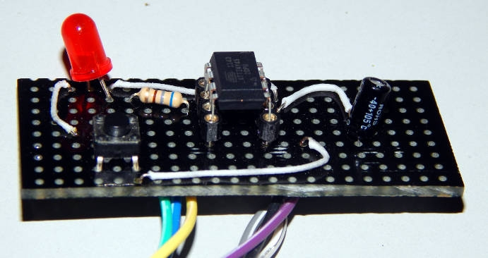
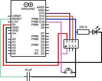
To program our ATtinies we'll construct a programming board with a DIP socket - so we can easily attach microcontrollers on it, program them, remove and use them on other breadboards/circuits. To do that, we'll need a spare Arduino board so we can use as our USB-to-SPI programmer. The board that I mounted was done following the instructions presented at this blog: http://brasilrobotics.blogspot.com.br/2012/03/aula-programando-attiny4585-com-arduino.html I believe they have better pictures of the board and its components over there, but the circuit is the same to the one presented at the picture that follows:
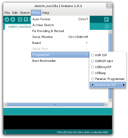
Before connecting this circuit to your Arduino board, you must program it with a special sketch that turns it into a AVRISP (AVR In-System Programmer).
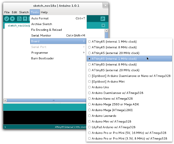
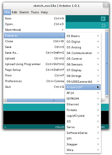 Once you've done that, connect your recently-created ATtiny programming board to the correct pins of your Arduino and configure your Arduino IDE use the Arduino as ISP and specify the board that you're programming:
I've always tried to bring connectivity into my Arduinos with an Ethernet Shield and even Ethernet SPI modules but I was never much pleased with the result. They somehow were very unstable, didn't run smoothly and, therefore, not much reliable (specially if your intention is to feed pets or something alike). Maybe it's just too much processing for the Arduino, to handle the HTTP requests and responses and still do what they're intended to (specially if you're working with interruptions, timers, PWM functions or combinations of them)
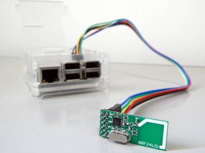
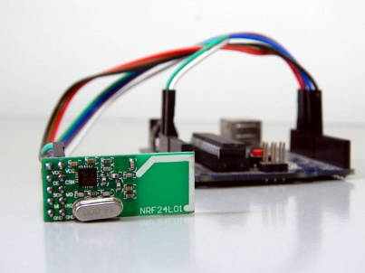
Recently I've found an outstanding solution bringing more computational power into the design and, at the same time, making the orchestration go wireless, which allows me to spread my nodes all over the house. I've done it using a Raspberry Pi B+ and a couple of NRF24L01 modules. The result has very satisfying and they could communicate over a 35 meters distance.
The Raspberry can handle HTTPS connections (to securely connect my sensor network into the web), host a database management system (so I don't even need to publish "sensing" data anywhere) and run many sorts of software (Python, Perl, PHP, C, Java, etc), being perfect as an intermediator between my private sensor network and the wild. The Arduinos can now just worry about handling very controlled and pre-formatted data and most of its concern is to implement what they actually must do. And better, wireless!, covering a much higher distance from my Access Point that they would using Ethernet cables.
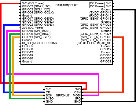
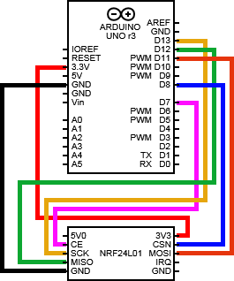
Having the NRF240L1 modules in hand, connect them following the circuit schematics below.
| Boards Pinout | ||
| Raspberry Pi B+ | Arduino | |
 |
 |
|
For both boards, Arduino and Raspberry, I used the same library package available at http://tmrh20.github.io/ (Optimized RF24 NRF24L01 Radio Library for Arduino - despite the name, this package also includes the libraries that we're going to use within the Raspberry). So, download the library, import it into the Arduino (Sketch->Import library). Prepare the environment at the Raspberry:
$ git clone https://github.com/TMRh20/RF24.git
$ cd RF24
$ sudo make install
As we're going to use JSON-C lib, install using the apt-get:
sudo apt-get install libjson0-devTalking about the sample application developed on the top of this infrastructure, I designed a solution where, somehow (through an SSH Internet connection or through a web service) I would request to the Raspberry some information located at the Arduino (in this case, the LED state located at pin 6). The Raspberry, in its turn, would then use the NRF240L1 module to talk to the Arduino, request the required information, receive it and give it back to the application (it should also manage timeout exceptions or any problems related to the communication towards the Arduino). This message could also mean an order, delegating the Arduino to do something (in this case, to change the LED's state). The image below illustrates the proposed
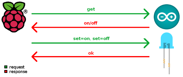
To do so, the Raspberry will always transmit data structured in a 16 bytes sized message object...
struct payload_request_t
{
  uint8_t number;
  uint8_t destination;
  char message[14];
};
... and the Arduino will always reply with a, also 16 bytes sized, message object:
struct payload_general_t
{
  uint8_t number;
  char message[15];
};
The request payload includes: a randomly created number as the message identifier; the destination node number identifier; and the message itself. The answer payload includes the request's number identifier and its reply message.
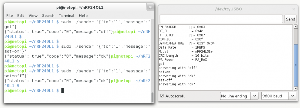
The application hosted at the Raspberry receives a JSON-structured string as the input parameter containing, apart from the destination node number and the message, an optional field "TTL" that represents a timeout delay tolerance for the transmission. This program always exits a JSON-structured string that describes if the message/request has been successfully transmitted and answered or not.
Input sample string:
{
	"to":"1",        // node 1
	"message":"get", // request/command
	"TTL":"2500"     // (optional) "time to live" (better said, "wait for")
}
Output sample string:
{
	"status":"true",  // it has been successfully transmitted
	"code":"0",       // error code, if any
	"message":"ok"    // replied message
}
Snapshot taken while running the presented solution.
Material list:
Source codes: