carr3r

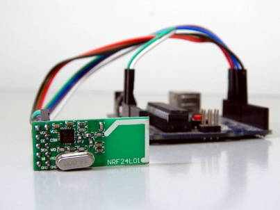
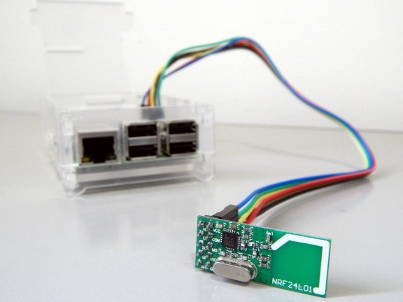
ESP8266 with FT232RL USB 2 Serial Adapter

Hello there ESP8266, you've just got a new fan!

The first time I played with ESP8266 "Wifi to Serial" module I used my USB-to-UART cable and Ubuntu, very straight forward.

For starters, two things to have in mind:

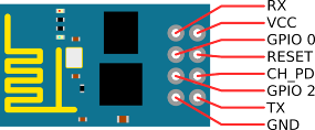
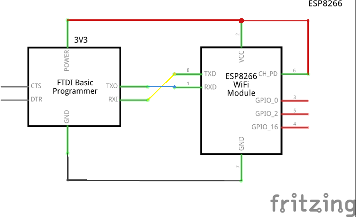
  • Use 3V3! (Also, if you're planning to use it with Arduino and/or other microcontrollers, use voltage regulators for every pin, since Arduino's HIGH voltage level is usually up to 5V).
  • ESP8266's CH_PD pin (which means Chip enabled) must be always HIGH, so connect it to VCC (putting it to LOW makes the chip enter Power Save mode).

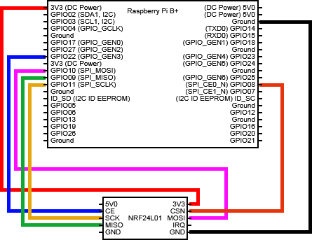
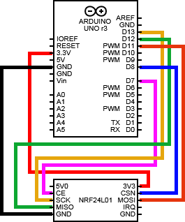
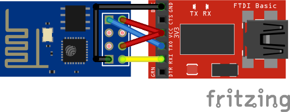
Having said that, wire both modules like schematic below:

 undefined

 undefined

 undefined

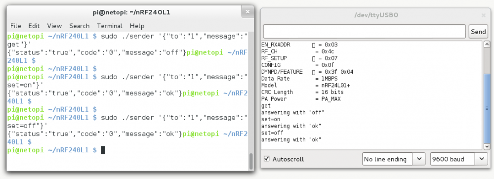
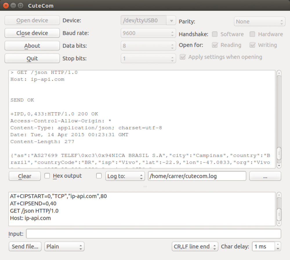
I confess I could not get minicom to work properly with this module, so I used cutecom (apt-get install cutecom) instead. You can get plenty information about this module at https://nurdspace.nl/ESP8266, so I really recommend taking a look at it.

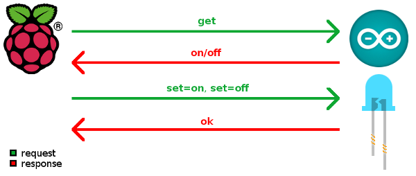
In this example I connected to the ESP, listed all Access-Points available, connected it to my personal AP and consumed an online Geo-IP API service with it. (Connection settings can be seen/checked at screenshot below)

undefined


 Command history:

// restart the module, just in case
AT+RST

OK
7!aS\0xcaS:\0xf1\0xfe\0x01\0xd91\0xb51\0x19\0xe2\0xd9\0xe6\0x0c<\0xff@b\0xe0
[Vendor:www.ai-thinker.com Version:0.9.2.4]

ready

// STAtion/client mode
AT+CWMODE=1


OK

// list all APs in within antenna's field area
AT+CWLAP

+CWLAP:(4,"Rep. Rancho Fundo",-X,"cc:a4:62:df:43:f0",1)
+CWLAP:(3,"Kakaroto4",-X,"28:c6:8e:b3:a7:12",1)
+CWLAP:(4,"RepX",-X,"c4:6e:1f:6d:7e:fc",6)
+CWLAP:(2,"raegui",-X,"c8:3a:35:1b:3b:98",6)
+CWLAP:(3,"sergioveio",-X,"5c:57:1a:22:6d:70",6)
+CWLAP:(4,"dlink-00F0",-X,"90:94:e4:fe:00:f0",2)
+CWLAP:(4,"SuiteMasterPranda",-X,"70:62:b8:80:4e:a3",6)
+CWLAP:(4,"arc",-X,"fc:b0:c4:d2:eb:7e",5)
+CWLAP:(4,"WakaWaka",-X,"e8:94:f6:eb:ba:10",6)
+CWLAP:(3,"net virtua 123",-X,"00:1d:d6:51:f5:d0",6)
+CWLAP:(4,"Dado",-X,"1c:7e:e5:be:7b:c6",6)
+CWLAP:(0,"S20CAM",-X,"00:40:96:57:99:32",8)
+CWLAP:(3,"EDSON A",-X,"00:1d:d5:01:c7:70",9)
+CWLAP:(1,"A.C.",-X,"00:23:cd:11:5e:b2",11)
+CWLAP:(3,"HP-Print-38-Deskjet 4640 series",-X,"a0:48:1c:65:5a:38",11)
+CWLAP:(4,"apto 113",-X,"70:54:d2:94:c9:9e",11)
+CWLAP:(4,"Zuza-Wireless",-X,"14:cf:e2:13:05:20",11)
+CWLAP:(4,"Chines",-X,"f4:ec:38:a0:74:bc",11)
+CWLAP:(4,"ed5a1c",-X,"d8:97:ba:87:82:bb",11)
+CWLAP:(4,"AP 133",-X,"a8:9d:d2:18:ee:0e",11)

OK
// setup connection 
AT+CWJAP="SSID","PASSWORD"


OK
// check IP received by DHCP
AT+CIFSR

10.0.0.103

OK
//set mutiple connection
AT+CIPMUX=1


OK
//setup TCP connectin on Port 80 at domain ip-api.com on connection id 0
AT+CIPSTART=0,"TCP","ip-api.com",80


OK
Linked

//using connection id 0, send the following 40 bytes (which will be a GET request on /json resource, similar to http://ip-api.com/json)
AT+CIPSEND=0,40

> GET /json HTTP/1.0
Host: ip-api.com


SEND OK

+IPD,0,433:HTTP/1.0 200 OK
Access-Control-Allow-Origin: *
Content-Type: application/json; charset=utf-8
Date: Tue, 14 Apr 2015 00:23:31 GMT
Content-Length: 277

{"as":"AS27699 TELEF\0xc3\0x94NICA BRASIL S.A","city":"Campinas","country":"Brazil","countryCode":"BR","isp":"Vivo","lat":-22.X,"lon":-47.X,"org":"Vivo","query":"xxx.xxx.xxx.xxx","region":"SP","regionName":"Sao Paulo","status":"success","timezone":"America/Sao_Paulo","zip":"13083"}

OK

Raspberry Pi B+ and Arduino talking through NRF24L01 modules

Arduino and NRF24L01

I've always tried to bring connectivity into my Arduinos with an Ethernet Shield and even Ethernet SPI modules but I was never much pleased with the result. They somehow were very unstable, didn't run smoothly and, therefore, not much reliable (specially if your intention is to feed pets or something alike). Maybe it's just too much processing for the Arduino, to handle the HTTP requests and responses and still do what they're intended to (specially if you're working with interruptions, timers, PWM functions or combinations of them)

Raspberry Pi B+ and NRF24L01

Recently I've found an outstanding solution bringing more computational power into the design and, at the same time, making the orchestration go wireless, which allows me to spread my nodes all over the house. I've done it using a Raspberry Pi B+ and a couple of NRF24L01 modules. The result has very satisfying and they could communicate over a 35 meters distance. 

The Raspberry can handle HTTPS connections (to securely connect my sensor network into the web), host a database management system (so I don't even need to publish "sensing" data anywhere) and run many sorts of software (Python, Perl, PHP, C, Java, etc), being perfect as an intermediator between my private sensor network and the wild. The Arduinos can now just worry about handling very controlled and pre-formatted data and most of its concern is to implement what they actually must do. And better, wireless!, covering a much higher distance from my Access Point that they would using Ethernet cables.

Having the NRF240L1 modules in hand, connect them following the circuit schematics below.

Boards Pinout
Raspberry Pi B+ Arduino
Raspberry Pi B+ pinout Arduino pinout  

For both boards, Arduino and Raspberry, I used the same library package available at http://tmrh20.github.io/ (Optimized RF24 NRF24L01 Radio Library for Arduino - despite the name, this package also includes the libraries that we're going to use within the Raspberry). So, download the library, import it into the Arduino (Sketch->Import library). Prepare the environment at the Raspberry:

$ git clone https://github.com/TMRh20/RF24.git
$ cd RF24
$ sudo make install

As we're going to use JSON-C lib, install using the apt-get:

sudo apt-get install libjson0-dev

Talking about the sample application developed on the top of this infrastructure, I designed a solution where, somehow (through an SSH Internet connection or through a web service) I would request to the Raspberry some information located at the Arduino (in this case, the LED state located at pin 6). The Raspberry, in its turn, would then use the NRF240L1 module to talk to the Arduino, request the required information, receive it and give it back to the application (it should also manage timeout exceptions or any problems related to the communication towards the Arduino). This message could also mean an order, delegating the Arduino to do something (in this case, to change the LED's state). The image below illustrates the proposed

undefined

To do so, the Raspberry will always transmit data structured in a 16 bytes sized message object...

struct payload_request_t
{
  uint8_t number;
  uint8_t destination;
  char message[14];
};

... and the Arduino will always reply with a, also 16 bytes sized, message object:

struct payload_general_t
{
  uint8_t number;
  char message[15];
};

The request payload includes: a randomly created number as the message identifier; the destination node number identifier; and the message itself. The answer payload includes the request's number identifier and its reply message.

The application hosted at the Raspberry receives a JSON-structured string as the input parameter containing, apart from the destination node number and the message, an optional field "TTL" that represents a timeout delay tolerance for the transmission. This program always exits a JSON-structured string that describes if the message/request has been successfully transmitted and answered or not.

Input sample string:

{
	"to":"1",        // node 1
	"message":"get", // request/command
	"TTL":"2500"     // (optional) "time to live" (better said, "wait for")
}

Output sample string:

{
	"status":"true",  // it has been successfully transmitted 
	"code":"0",       // error code, if any
	"message":"ok"    // replied message
}

 Snapshot taken while running the presented solution.

undefined

Material list:

 Source codes:

Home